

In this project, we will learn about Stepper Motors, how the Raspberry Pi Stepper Motor Interface works and how to control a Stepper Motor using Raspberry Pi and L298N Motor Driver Module.
Overview
If you remember the previous Raspberry Pi Tutorials, we have seen HOW TO CONTROL A DC MOTOR USING RASPBERRY PI and also HOW TO CONTROL A SERVO MOTOR USING RASPBERRY PI.
Stepper Motors can be categorized between Servo Motors and DC Motors as you can control the angular position of the shaft as well as rotate the shaft freely in either direction.
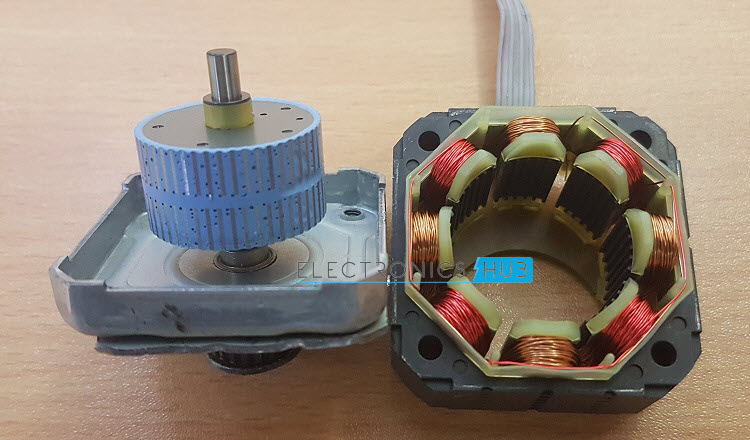
I have already discussed about stepper motors, types of stepper motors, internal structure of a stepper motor and also how to design a stepper motor control circuit in STEPPER MOTOR CONTROL USING ARDUINO project.
So, I suggest you to refer to that project once before continuing with the Raspberry Pi Stepper Motor Interface.
Driving a Stepper Motor
It is important for you to identify your stepper motor i.e. whether it is a Unipolar Stepper Motor or a Bipolar Stepper Motor. Because, the driving techniques for each of these motor is different.
In this project, I’ll be using a simple 12V Bipolar Stepper Motor. To drive this Stepper Motor, we need a motor driver module like L293D or L298N. Both these module work great with the 12V Stepper Motor. So, choosing the driver module is up to you. For this project, I have chosen the L298N Motor Driver Module.
The main advantage of a Stepper Motor over a Servo Motor is that complete rotation of the motor’s shaft is divided into steps and you can precisely position the Stepper Motor by carefully energizing the Motor Coils.
Even though there is no feedback mechanism like in a Servo Motor, a Stepper Motor with smaller step angles can provide very accurate angular positioning.
Typically, almost all commercially available Stepper Motors comes with a step angle of 1.80. So, for a complete 3600 degree rotation, it will have a step count of 200.
In order to increase the accuracy of the Stepper Motor i.e. to achieve a bit more precise angular positioning of the shaft, you can use a technique called “Half Stepping”.

Half Stepping is a technique where instead of energizing a single phase at a time, we will be use a combination of one phase and two phase energizing. With this technique, you can achieve even smaller resolution of 400 steps and a smoother operation.
Raspberry Pi Stepper Motor Interface
Almost all advanced CNC Machines and Industrial Pick-n-Place Robots use Stepper Motors in them. Raspberry Pi on the other hand is a tiny computer that is being used in a wide range of applications like Robotics, Home Automation, Industrial Automation an many other.
So, interfacing a Stepper Motor with Raspberry Pi will be interesting as you can implement this interface in all the above mentioned applications.
A 12V Bipolar Stepper Motor draws about 350mA to 500mA of current. Hence, we need a dedicated driver circuit while working on the Raspberry Pi Stepper Motor Interface.
Since I have used a Bipolar Stepper Motor, I only need four control wires. This can be done with the help of many different modules or drivers like L293D, ULN2003 or L298N.
In case of a Unipolar Stepper Motor, there are multiple ways you can wire it to the Driver Module. Typically, a Unipolar Stepper Motor will have either 5 or 6 wires. So, you need to use ULN2003 or wire it a Bipolar Stepper Motor.
Circuit Diagram
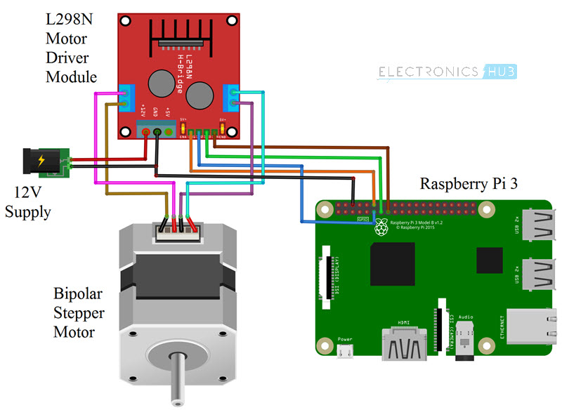
The following image shows the connection diagram of the Raspberry Pi Stepper Motor Control using L298N. It is implemented using Fritzing Application.
Components Required
- Raspberry Pi 3 Model B
- 12V Bipolar Stepper Motor
- L298N Motor Driver Module
- 12V Motor Power Supply
- Power Supply for Raspberry Pi
- Connecting Wires
- Computer
Circuit Design
The inputs to the Motor Driver Module i.e. IN1, IN2, IN3 and IN4 are connected to the Physical Pins 11, 12, 13 and 15 i.e. GPIO17, GPIO18, GPIO27 and GPIO22 of the Raspberry Pi.
One set of the Motor Coils are connected to OUT1 and OUT2 of the Motor Driver and the other set is connected to OUT3 and OUT4.
A 12V external power supply is given to the Motor Driver Module and the ground terminals of the L298N Motor Driver Module and the Raspberry Pi are made common.
A separate 5V supply is given to the Raspberry Pi.
Code
The programming part of the project is implemented using Python. The Python script for Controlling a Stepper Motor using Raspberry Pi and L298N Motor Driver Module is given below.
| import RPi.GPIO as GPIO | |
| import time | |
| out1 = 13 | |
| out2 = 11 | |
| out3 = 15 | |
| out4 = 12 | |
| i=0 | |
| positive=0 | |
| negative=0 | |
| y=0 | |
| GPIO.setmode(GPIO.BOARD) | |
| GPIO.setup(out1,GPIO.OUT) | |
| GPIO.setup(out2,GPIO.OUT) | |
| GPIO.setup(out3,GPIO.OUT) | |
| GPIO.setup(out4,GPIO.OUT) | |
| print “First calibrate by giving some +ve and -ve values…..” | |
| try: | |
| while(1): | |
| GPIO.output(out1,GPIO.LOW) | |
| GPIO.output(out2,GPIO.LOW) | |
| GPIO.output(out3,GPIO.LOW) | |
| GPIO.output(out4,GPIO.LOW) | |
| x = input() | |
| if x>0 and x<=400: | |
| for y in range(x,0,–1): | |
| if negative==1: | |
| if i==7: | |
| i=0 | |
| else: | |
| i=i+1 | |
| y=y+2 | |
| negative=0 | |
| positive=1 | |
| #print((x+1)-y) | |
| if i==0: | |
| GPIO.output(out1,GPIO.HIGH) | |
| GPIO.output(out2,GPIO.LOW) | |
| GPIO.output(out3,GPIO.LOW) | |
| GPIO.output(out4,GPIO.LOW) | |
| time.sleep(0.03) | |
| #time.sleep(1) | |
| elif i==1: | |
| GPIO.output(out1,GPIO.HIGH) | |
| GPIO.output(out2,GPIO.HIGH) | |
| GPIO.output(out3,GPIO.LOW) | |
| GPIO.output(out4,GPIO.LOW) | |
| time.sleep(0.03) | |
| #time.sleep(1) | |
| elif i==2: | |
| GPIO.output(out1,GPIO.LOW) | |
| GPIO.output(out2,GPIO.HIGH) | |
| GPIO.output(out3,GPIO.LOW) | |
| GPIO.output(out4,GPIO.LOW) | |
| time.sleep(0.03) | |
| #time.sleep(1) | |
| elif i==3: | |
| GPIO.output(out1,GPIO.LOW) | |
| GPIO.output(out2,GPIO.HIGH) | |
| GPIO.output(out3,GPIO.HIGH) | |
| GPIO.output(out4,GPIO.LOW) | |
| time.sleep(0.03) | |
| #time.sleep(1) | |
| elif i==4: | |
| GPIO.output(out1,GPIO.LOW) | |
| GPIO.output(out2,GPIO.LOW) | |
| GPIO.output(out3,GPIO.HIGH) | |
| GPIO.output(out4,GPIO.LOW) | |
| time.sleep(0.03) | |
| #time.sleep(1) | |
| elif i==5: | |
| GPIO.output(out1,GPIO.LOW) | |
| GPIO.output(out2,GPIO.LOW) | |
| GPIO.output(out3,GPIO.HIGH) | |
| GPIO.output(out4,GPIO.HIGH) | |
| time.sleep(0.03) | |
| #time.sleep(1) | |
| elif i==6: | |
| GPIO.output(out1,GPIO.LOW) | |
| GPIO.output(out2,GPIO.LOW) | |
| GPIO.output(out3,GPIO.LOW) | |
| GPIO.output(out4,GPIO.HIGH) | |
| time.sleep(0.03) | |
| #time.sleep(1) | |
| elif i==7: | |
| GPIO.output(out1,GPIO.HIGH) | |
| GPIO.output(out2,GPIO.LOW) | |
| GPIO.output(out3,GPIO.LOW) | |
| GPIO.output(out4,GPIO.HIGH) | |
| time.sleep(0.03) | |
| #time.sleep(1) | |
| if i==7: | |
| i=0 | |
| continue | |
| i=i+1 | |
| elif x<0 and x>=–400: | |
| x=x*–1 | |
| for y in range(x,0,–1): | |
| if positive==1: | |
| if i==0: | |
| i=7 | |
| else: | |
| i=i–1 | |
| y=y+3 | |
| positive=0 | |
| negative=1 | |
| #print((x+1)-y) | |
| if i==0: | |
| GPIO.output(out1,GPIO.HIGH) | |
| GPIO.output(out2,GPIO.LOW) | |
| GPIO.output(out3,GPIO.LOW) | |
| GPIO.output(out4,GPIO.LOW) | |
| time.sleep(0.03) | |
| #time.sleep(1) | |
| elif i==1: | |
| GPIO.output(out1,GPIO.HIGH) | |
| GPIO.output(out2,GPIO.HIGH) | |
| GPIO.output(out3,GPIO.LOW) | |
| GPIO.output(out4,GPIO.LOW) | |
| time.sleep(0.03) | |
| #time.sleep(1) | |
| elif i==2: | |
| GPIO.output(out1,GPIO.LOW) | |
| GPIO.output(out2,GPIO.HIGH) | |
| GPIO.output(out3,GPIO.LOW) | |
| GPIO.output(out4,GPIO.LOW) | |
| time.sleep(0.03) | |
| #time.sleep(1) | |
| elif i==3: | |
| GPIO.output(out1,GPIO.LOW) | |
| GPIO.output(out2,GPIO.HIGH) | |
| GPIO.output(out3,GPIO.HIGH) | |
| GPIO.output(out4,GPIO.LOW) | |
| time.sleep(0.03) | |
| #time.sleep(1) | |
| elif i==4: | |
| GPIO.output(out1,GPIO.LOW) | |
| GPIO.output(out2,GPIO.LOW) | |
| GPIO.output(out3,GPIO.HIGH) | |
| GPIO.output(out4,GPIO.LOW) | |
| time.sleep(0.03) | |
| #time.sleep(1) | |
| elif i==5: | |
| GPIO.output(out1,GPIO.LOW) | |
| GPIO.output(out2,GPIO.LOW) | |
| GPIO.output(out3,GPIO.HIGH) | |
| GPIO.output(out4,GPIO.HIGH) | |
| time.sleep(0.03) | |
| #time.sleep(1) | |
| elif i==6: | |
| GPIO.output(out1,GPIO.LOW) | |
| GPIO.output(out2,GPIO.LOW) | |
| GPIO.output(out3,GPIO.LOW) | |
| GPIO.output(out4,GPIO.HIGH) | |
| time.sleep(0.03) | |
| #time.sleep(1) | |
| elif i==7: | |
| GPIO.output(out1,GPIO.HIGH) | |
| GPIO.output(out2,GPIO.LOW) | |
| GPIO.output(out3,GPIO.LOW) | |
| GPIO.output(out4,GPIO.HIGH) | |
| time.sleep(0.03) | |
| #time.sleep(1) | |
| if i==0: | |
| i=7 | |
| continue | |
| i=i–1 | |
| except KeyboardInterrupt: | |
| GPIO.cleanup() |
Working of the Project
This purpose of this simple project is just to understand how to Interface a Stepper Motor with Raspberry Pi and L298N. The working of the project is very simple and is explained here.
Initially, you need to calibrate the Stepper Motor by giving some random values so that the steps will be locked. Here, a positive value (like 30, for example) will make the Stepper Motor to rotate in clockwise direction and a negative value (like -30) will make it to rotate in the anti-clockwise direction.
After this initial calibration, you can enter any value and the Stepper Motor will move to that position. Since we are implementing a Half Stepping Technique, the total number of steps is 400. So, if you enter 100, the Stepper Motor will rotate 900 in clock wise direction.
Similarly, by entering other values (either positive or negative) you can accurately control the position of your Stepper Motor.
Applications
Controlling a Stepper Motor with Raspberry Pi will enable us to use this interface in a variety of projects and applications like:
- Robotics
- CNC Plotters
- 3D Printing
- Home Automation
- Industrial Automation


